Last time we have built a URDF model of a drone and spawned it in Gazebo. Today we will make a Gazebo plugin to control the drone.
Our goal is to create a Gazebo Model Plugin that will interface with ROS and add forces to the model based on the desired motor speeds, such that the drone will be able to fly. This is the very basic level of control, which we need to implement.
The plugin ROS interface will be as follows:
- Drone pose in the world frame of reference will be published on the /pose topic. We will create a kair_drone/Pose message type for easy orientation representation using RPY angles.
- The plugin will also publish the frame pose using a TF broadcaster on the /tf topic.
- The plugin will listen for the kair_drone/MotorSpeed message on the /motor_speeds_cmd topic and apply the simulated forces to the model.
- The plugin parameters will be defined as the SDF elements in the xacro model file.
As usual, the code is all available in the repository.
1. Creating the messages
First, we shall create the two message types necessary. The Pose message shall carry the complete position and orientation information about the model in simulation and the MotorSpeed will define the desired speeds for the six motors of the model.
The Pose message is defined in the msg/Pose.msg file as follows:
float32 x
float32 y
float32 z
float32 roll
float32 pitch
float32 yaw
float32 y
float32 z
float32 roll
float32 pitch
float32 yaw
There are several message types defined in the standard geometry_msgs package that we could use instead, e.g. Pose or Transform. These involve the conventional ROS quaternion representation though and it will be easier for us to represent the orientation as RPY angles explicitly.
The MotorSpeed message is defined in the msg/MotorSpeed.msg file:
string[] name
float32[] velocity
float32[] velocity
Next, we have to modify the CMakeLists.txt and the package.xml to enable message building. Make sure that the package has the following dependencies:
- geometry_msgs
- sensor_msgs
- std_msgs
- tf
- message_generation
Next, make sure that the message definition and message generation sections in the CMakeLists.txt look like this:
## Generate messages in the 'msg' folder
add_message_files(
FILES
Pose.msg
MotorSpeed.msg
)
add_message_files(
FILES
Pose.msg
MotorSpeed.msg
)
## Generate added messages and services with any dependencies listed here
generate_messages(
DEPENDENCIES
geometry_msgs
sensor_msgs
std_msgs
)
generate_messages(
DEPENDENCIES
geometry_msgs
sensor_msgs
std_msgs
)
Rebuild the project now and re-source the setup files:
cd ~/catkin_ws
catkin build
source devel/setup.bash
2. Preparing the build system for the Gazebo plugin
The following changes need to be made to the CMakeLists.txt in order to build the Gazebo plugin:
- in the system dependencies section:
## System dependencies are found with CMake's conventions
# find_package(Boost REQUIRED COMPONENTS system)
find_package(gazebo REQUIRED)
# find_package(Boost REQUIRED COMPONENTS system)
find_package(gazebo REQUIRED)
- in the Build section:
## Specify additional locations of header files
## Your package locations should be listed before other locations
include_directories(
# include
${catkin_INCLUDE_DIRS}
${GAZEBO_INCLUDE_DIRS}
)
link_directories(
${GAZEBO_LIBRARY_DIRS}
)
list(APPEND CMAKE_CXX_FLAGS "${GAZEBO_CXX_FLAGS}")
## Your package locations should be listed before other locations
include_directories(
# include
${catkin_INCLUDE_DIRS}
${GAZEBO_INCLUDE_DIRS}
)
link_directories(
${GAZEBO_LIBRARY_DIRS}
)
list(APPEND CMAKE_CXX_FLAGS "${GAZEBO_CXX_FLAGS}")
- and finally, we add the plugin target:
add_library(drone_plugin SHARED src/drone_plugin.cpp)
target_link_libraries(drone_plugin ${GAZEBO_LIBRARIES} ${catkin_LIBRARIES})
target_link_libraries(drone_plugin ${GAZEBO_LIBRARIES} ${catkin_LIBRARIES})
3. Creating the plugin
Let's begin by creating the boilerplate Model plugin file src/drone_plugin.cpp:
#include <iostream>
#include <gazebo/gazebo.hh>
#include <gazebo/physics/physics.hh>
#include <gazebo/common/common.hh>
class DronePlugin : public gazebo::ModelPlugin {
public:
DronePlugin() : gazebo::ModelPlugin() {
std::cout << "Starting drone_plugin" << std::endl;
}
virtual ~DronePlugin() {
std::cout << "Closing drone_plugin" << std::endl;
}
void Load(gazebo::physics::ModelPtr parent, sdf::ElementPtr sdf) {
_model = parent;
}
private:
gazebo::physics::ModelPtr _model;
};
GZ_REGISTER_MODEL_PLUGIN(DronePlugin)
This is the very basic plugin file structure that we will gradually expand. It is a good idea at this point to check whether the build system is set up properly:
cd ~/catkin_ws
catkin build
4. Reading the plugin parameters from SDF
If we want to specify the plugin parameters in the model SDF (and we do), we can then read them inside the plugin's Load() function. We will read the updateRate parameter (how often the pose messages shall be published), publishTf parameter (whether to publish the pose on /tf as well), rotorThrustCoeff (a coefficient that relates the rotor lift to its rotational speed) and rotorTorqueCoeff (which relates the rotor torque to its speed). This can be done by modifying the Load() function as:
void Load(gazebo::physics::ModelPtr parent, sdf::ElementPtr sdf) {
_model = parent;
if (sdf->HasElement("updateRate")) {
_rate = sdf->GetElement("updateRate")->Get<double>();
} else {
_rate = 100.0;
}
if (sdf->HasElement("publishTf")) {
_publish_tf = sdf->GetElement("publishTf")->Get<bool>();
} else {
_publish_tf = true;
}
if (sdf->HasElement("rotorThrustCoeff")) {
_rotor_thrust_coeff =
sdf->GetElement("rotorThrustCoeff")->Get<double>();
} else {
_rotor_thrust_coeff = 0.00025;
}
if (sdf->HasElement("rotorTorqueCoeff")) {
_rotor_torque_coeff =
} else {
_rotor_thrust_coeff = 0.00025;
}
if (sdf->HasElement("rotorTorqueCoeff")) {
_rotor_torque_coeff =
sdf->GetElement("rotorTorqueCoeff")->Get<double>();
} else {
_rotor_torque_coeff = 0.0000074;
}
}
} else {
_rotor_torque_coeff = 0.0000074;
}
}
Of course, the new variables also have to be added to the private section of the DronePlugin class:
private:
double _rate;
bool _publish_tf;
double _rotor_thrust_coeff;
double _rotor_torque_coeff;
double _rate;
bool _publish_tf;
double _rotor_thrust_coeff;
double _rotor_torque_coeff;
5. Creating the ROS node
In order to enable the ROS interface, we need to create a ROS node handle during the plugin initialization. This is also done in the Load() function:
void Load(gazebo::physics::ModelPtr parent, sdf::ElementPtr sdf) {
...
if (!ros::isInitialized()) {
int argc = 0;
char** argv = NULL;
ros::init(argc, argv, "kair_drone",
...
if (!ros::isInitialized()) {
int argc = 0;
char** argv = NULL;
ros::init(argc, argv, "kair_drone",
ros::init_options::NoSigintHandler);
}
_nh = new ros::NodeHandle("");
_pose_pub = _nh->advertise<kair_drone::Pose>("pose", 100);
_cmd_sub = _nh->subscribe("motor_speed_cmd", 100,
}
_nh = new ros::NodeHandle("");
_pose_pub = _nh->advertise<kair_drone::Pose>("pose", 100);
_cmd_sub = _nh->subscribe("motor_speed_cmd", 100,
&DronePlugin::onMotorSpeedsMsg, this);
_ros_thread =
_ros_thread =
std::thread(std::bind(&DronePlugin::rosThread, this));
}
}
It is necessary to check whether the ROS was already initialized. Since we are going to launch Gazebo through gazebo_ros, it most likely was. We create a new ROS handle _nh and the /pose publisher and the /motor_speed_cmd subscriber as well. Furthermore, we also create a separate thread for ROS to spin in.
The onMotorSpeedsMsg() callback looks simple enough:
void onMotorSpeedsMsg(const kair_drone::MotorSpeed::ConstPtr& msg) {
_cmd_mtx.lock();
_motor_speed_msg = *msg;
_cmd_mtx.unlock();
}
_cmd_mtx.lock();
_motor_speed_msg = *msg;
_cmd_mtx.unlock();
}
The rosThread() is the place where the ROS gets updated and where we will publish the model pose from:
void rosThread() {
ros::Rate rate(_rate);
while (ros::ok()) {
ros::spinOnce();
publishDronePose();
rate.sleep();
}
}
ros::Rate rate(_rate);
while (ros::ok()) {
ros::spinOnce();
publishDronePose();
rate.sleep();
}
}
We might as well define the publishDronePose() method now:
void publishDronePose() {
_pose_mtx.lock();
gazebo::math::Pose pose = _pose;
_pose_mtx.unlock();
gazebo::math::Vector3 rpy = pose.rot.GetAsEuler();
tf::Quaternion q(pose.rot.x, pose.rot.y, pose.rot.z, pose.rot.w);
tf::Matrix3x3 m(q);
double roll, pitch, yaw;
m.getRPY(roll, pitch, yaw);
kair_drone::Pose pose_msg;
pose_msg.x = pose.pos.x;
pose_msg.y = pose.pos.y;
pose_msg.z = pose.pos.z;
pose_msg.roll = roll;
pose_msg.pitch = -pitch;
pose_msg.yaw = yaw;
_pose_pub.publish(pose_msg);
if (_publish_tf) {
tf::Transform T;
T.setOrigin(tf::Vector3(pose.pos.x, pose.pos.y, pose.pos.z));
T.setRotation(
tf::Quaternion(pose.rot.x, pose.rot.y,
pose.rot.z, pose.rot.w));
_tf.sendTransform(
_tf.sendTransform(
tf::StampedTransform(T, ros::Time::now(),
"world", "drone"));
}
}
}
}
Here you can see how the conversion from the conventional quaternion orientation to RPY is done. Notice also that we multiply pitch by -1. This is done in order to match the frame orientation in simulation with the common aircraft convention where the Z axis is expected to be directed downwards.
Please consult the complete code in the repository to see which headers and what data fields need to be added to the source at this point.
6. Adding the forces
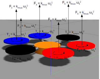
The idea behind simulating the rotor equipped drone model is that at each step of the simulation we add an array of forces and torques to the drone body that correspond to the forces that would be exerted by the propellers (see Fig. 1).
 |
| Fig. 1. Adding forces and torques to the model. |
The forces for each of the propellers are calculated as:
The sgn() function is there to make it possible to define the direction of the torque by specifying the sign of the angular speed of the rotor.
Let us begin by adding yet another callback in the Load() function. This will make the onUpdate() method called at each step of the simulation:
void Load(gazebo::physics::ModelPtr parent, sdf::ElementPtr sdf) {
...
_updateConnection =
...
_updateConnection =
gazebo::event::Events::ConnectWorldUpdateBegin(
std::bind(&DronePlugin::onUpdate, this));
}
}
The onUpdate() function updates the _pose (so only now will the publishDronePose work properly), and calls the updateThrust() method:
void onUpdate() {
_pose_mtx.lock();
_pose = _model->GetWorldPose();
_pose_mtx.unlock();
updateThrust();
}
_pose_mtx.lock();
_pose = _model->GetWorldPose();
_pose_mtx.unlock();
updateThrust();
}
The updateThrust() method looks up the child links of the model (so that is why we have modelled them as separate links attached by the revolute joints!) according to the name field in the MotorSpeed message, calculates the force and torque for each, and applies those to the link:
void updateThrust() {
_cmd_mtx.lock();
kair_drone::MotorSpeed cmd = _motor_speed_msg;
_cmd_mtx.unlock();
int n = cmd.name.size();
for (int i = 0; i < n; ++i) {
double thrust = calculateThrust(cmd.velocity[i]);
double torque = calculateTorque(cmd.velocity[i]);
gazebo::physics::LinkPtr link = _model->GetLink(cmd.name[i]);
if (link != NULL) {
link->AddLinkForce(gazebo::math::Vector3(0, 0, thrust));
link->AddRelativeTorque(gazebo::math::Vector3(0, 0, torque));
}
}
}
AddLinkForce() and AddRelativeTorque() are the appropriate Gazebo methods to use here. The Gazebo documentation is sometimes quite insufficient in this regard, but these methods apply the force and torque respectively as an impulse; just in that one step of the simulation. What remains now is to calculate the force and torque for each of the propellers:
double calculateThrust(double w) {
double thrust = _rotor_thrust_coeff * w * w;
return thrust;
double thrust = _rotor_thrust_coeff * w * w;
return thrust;
}
double calculateTorque(double w) {
double torque = copysign(_rotor_torque_coeff * w * w, w);
return torque;
double torque = copysign(_rotor_torque_coeff * w * w, w);
return torque;
}
7. Adding the plugin to the drone model
We can build the plugin now and add it to the drone model defined in urdf/drone.urdf.xacro. It goes right towards the end of the file:
...
<gazebo>
<plugin name="drone_plugin" filename="libdrone_plugin.so">
<updateRate>100</updateRate>
<publishTf>true</publishTf>
<rotorThrustCoeff>0.00025</rotorThrustCoeff>
<rotorTorqueCoeff>0.0000074</rotorTorqueCoeff>
</plugin>
</gazebo>
<plugin name="drone_plugin" filename="libdrone_plugin.so">
<updateRate>100</updateRate>
<publishTf>true</publishTf>
<rotorThrustCoeff>0.00025</rotorThrustCoeff>
<rotorTorqueCoeff>0.0000074</rotorTorqueCoeff>
</plugin>
</gazebo>
</robot>
When we launch the program now:
roslaunch kair_drone gazebo.launch
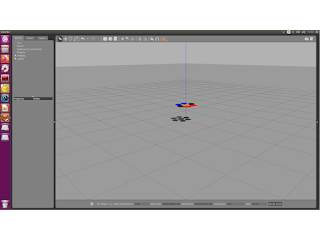
we should see the /pose and /motor_speed_cmd visible in rostopic list. And we can now watch the drone fly (uncontrollably) up (Fig. 2)!
rostopic pub /motor_speed_cmd kair_drone/MotorSpeed "name: ['propeller1', 'propeller2', 'propeller3', 'propeller4', 'propeller5', 'propeller6']
velocity: [125, -125, 125, -125, 125, -125]" -1
velocity: [125, -125, 125, -125, 125, -125]" -1
 |
| Fig. 2. Drone flying up! |


